
FINITE ELEMENT MODELING USING ABAQUS
3rd Fan Votes Winner - 2015 edition
Project Description:
A Finite Element Model (FEM) is very useful in understanding the thermo-mechanical behavior of any physical process. It is hence used widely in industrial applications as it has the capability to save time and overall cost of the product. Today almost every industry and most of the educational institutions in the world use ABAQUS to simulate a process, analyse the observations and validate it using the experimental results. Some of the models with potential industrial application have been discussed in this project. The FEA models which have been created using ABAQUS are as follows:
1. Machining
2. Friction Stir Welding
3. Drilling
4. Crack propagation model.
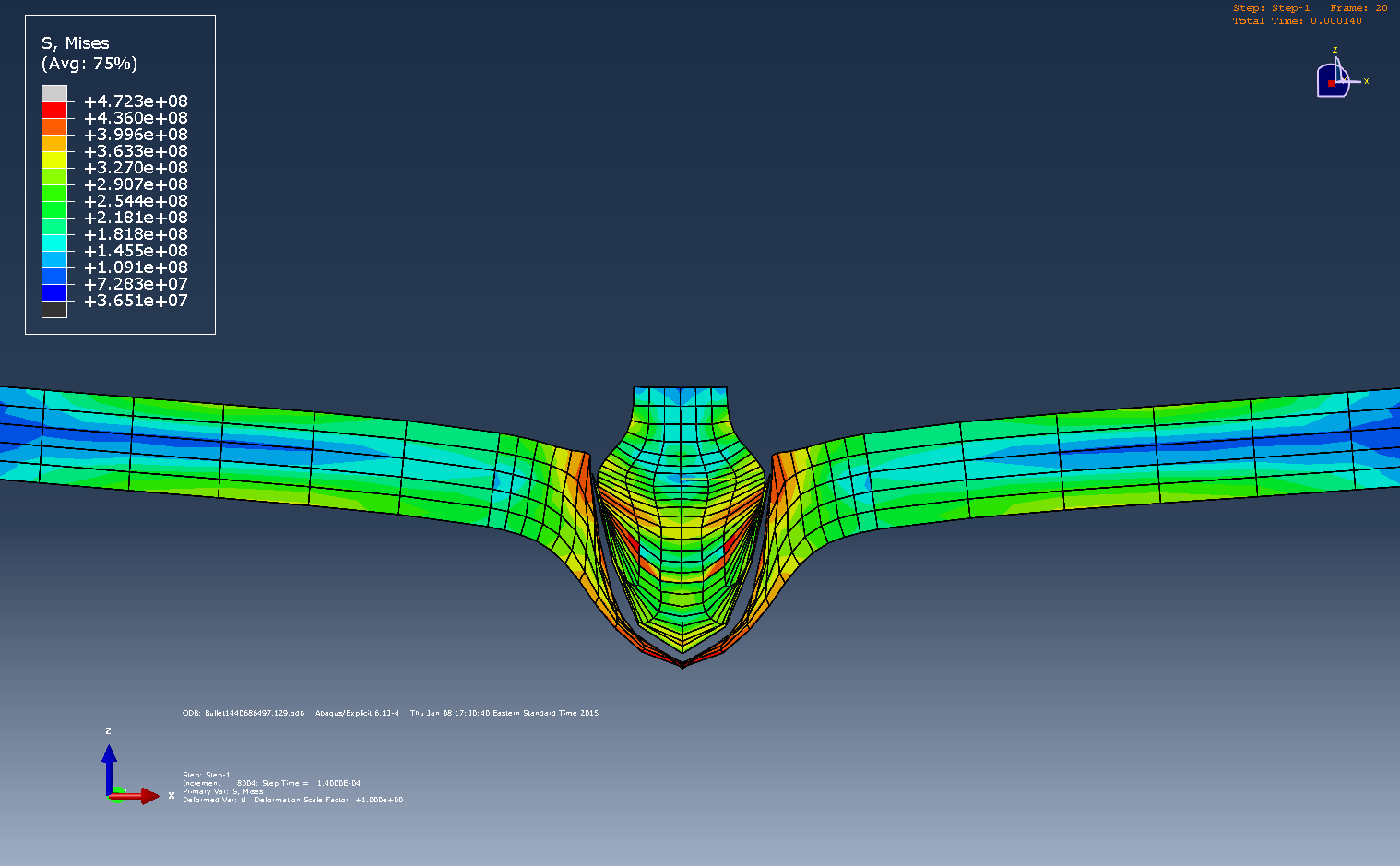
5. Bullet Impact
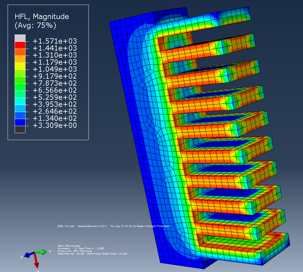
6. Thermal Analysis of Fins used in Automobiles.
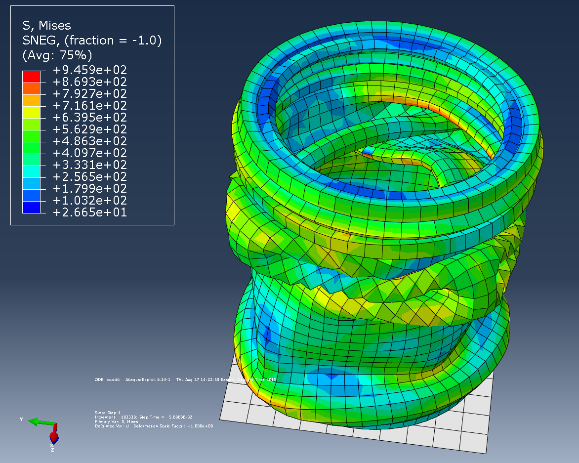
7. Crushed can model
DETAILED DESCRIPTION:-
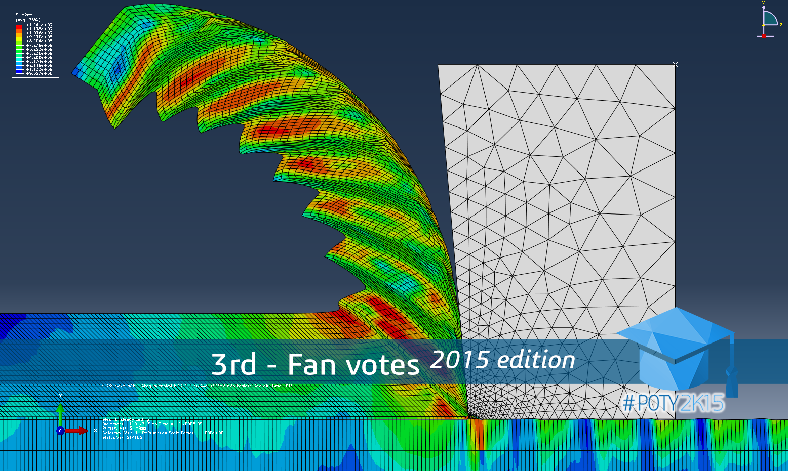
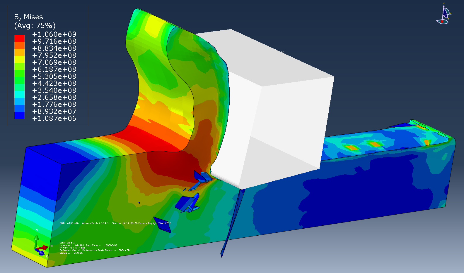
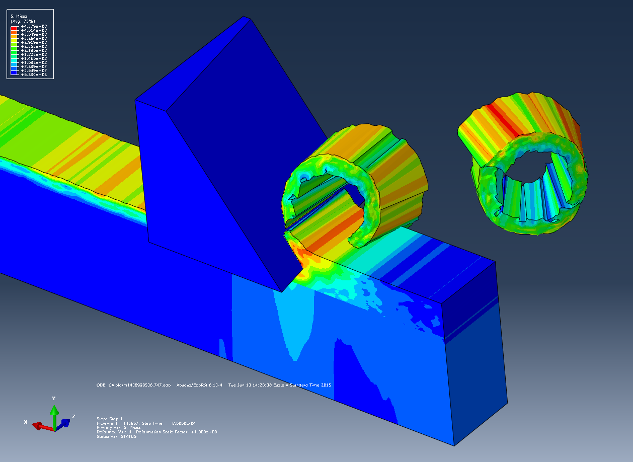
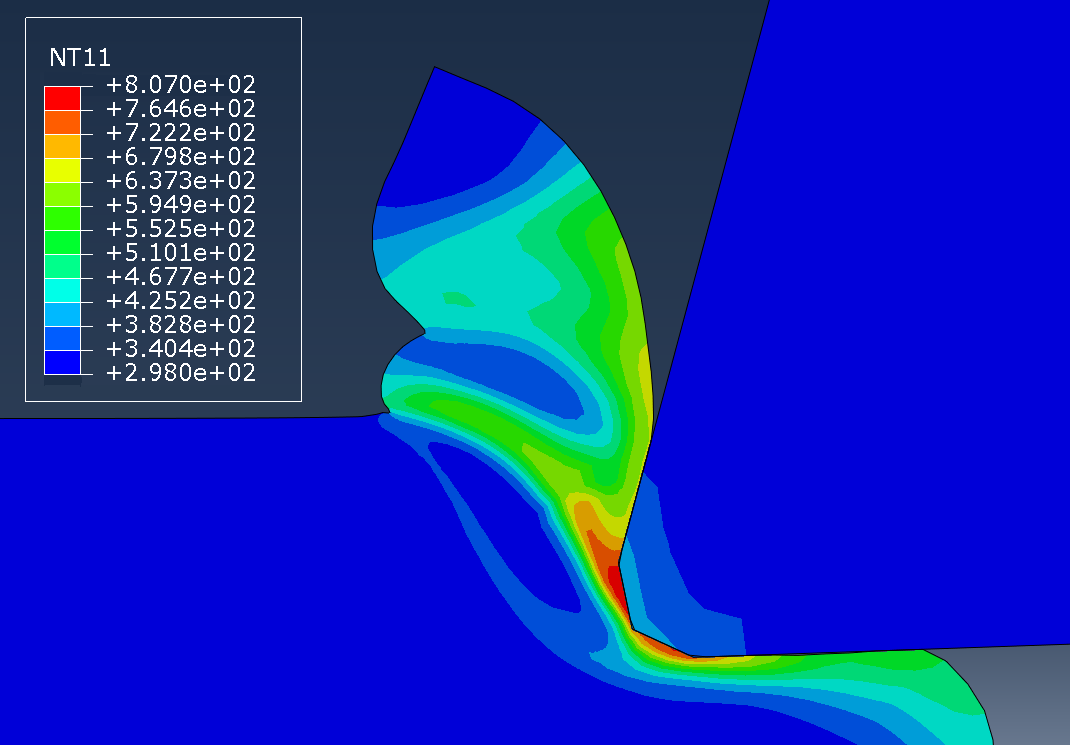
1. MACHINING MODEL:
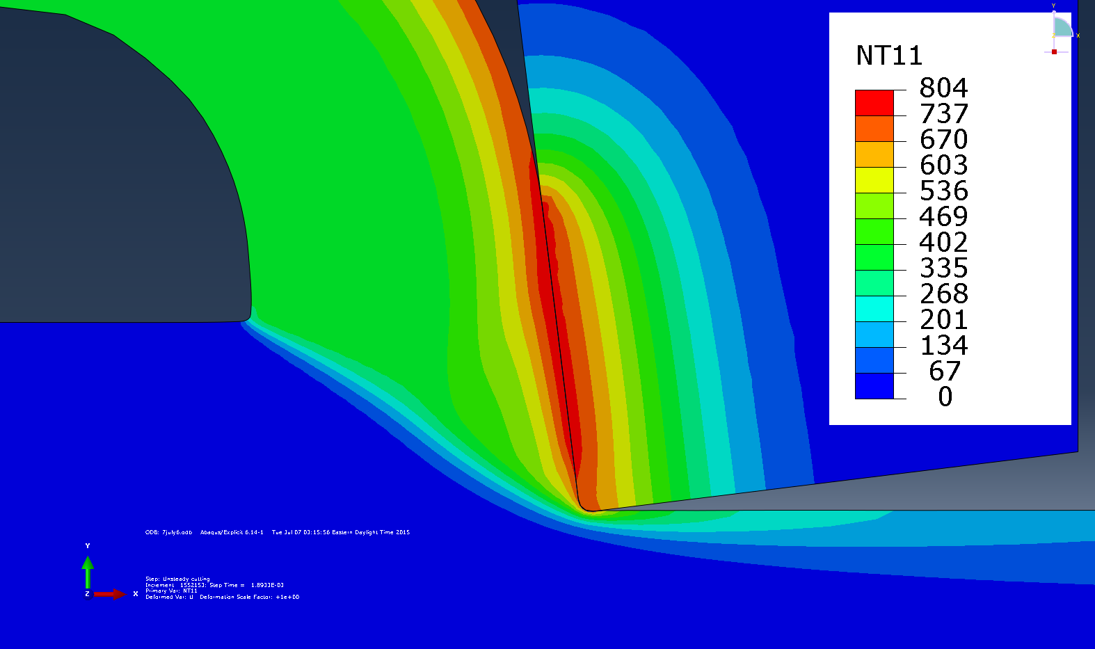
- In this project, two-dimensional and three-dimensional finite element models of chip formation during machining process of different materials like steel, nickel, titanium and aluminum are presented.
- A FEM model of chip formation process helps in determining the chip morphology, temperature and stress distribution which is critical in determining the correct process parameters during machining process.
- Modelling machining process of steel is always challenging as compared to other materials since phase transformation occurs during 700-800 deg C.
- The steel model involved use of FORTRAN code to develop user subroutines like VUHARD and VUSDFLD in order to include two constitutive models for the two different phases - ferrite-pearlite and austenite.
- For the serrated chip formation process during machining of nickel and titanium alloys, a modified Johnson cook constitutive model was incorporated using FORTRAN.
- The simulation results were successfully validated using the experimental data and the results published in scientific journals.
- These FEM models can further be applied to predict the chip morphology, temperature and stress distribution in machining of several other steel, nickel, aluminum and titanium alloys by just changing the material properties.
2. FRICTION STIR WELDING (FSW) MODEL:
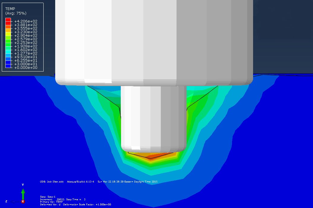
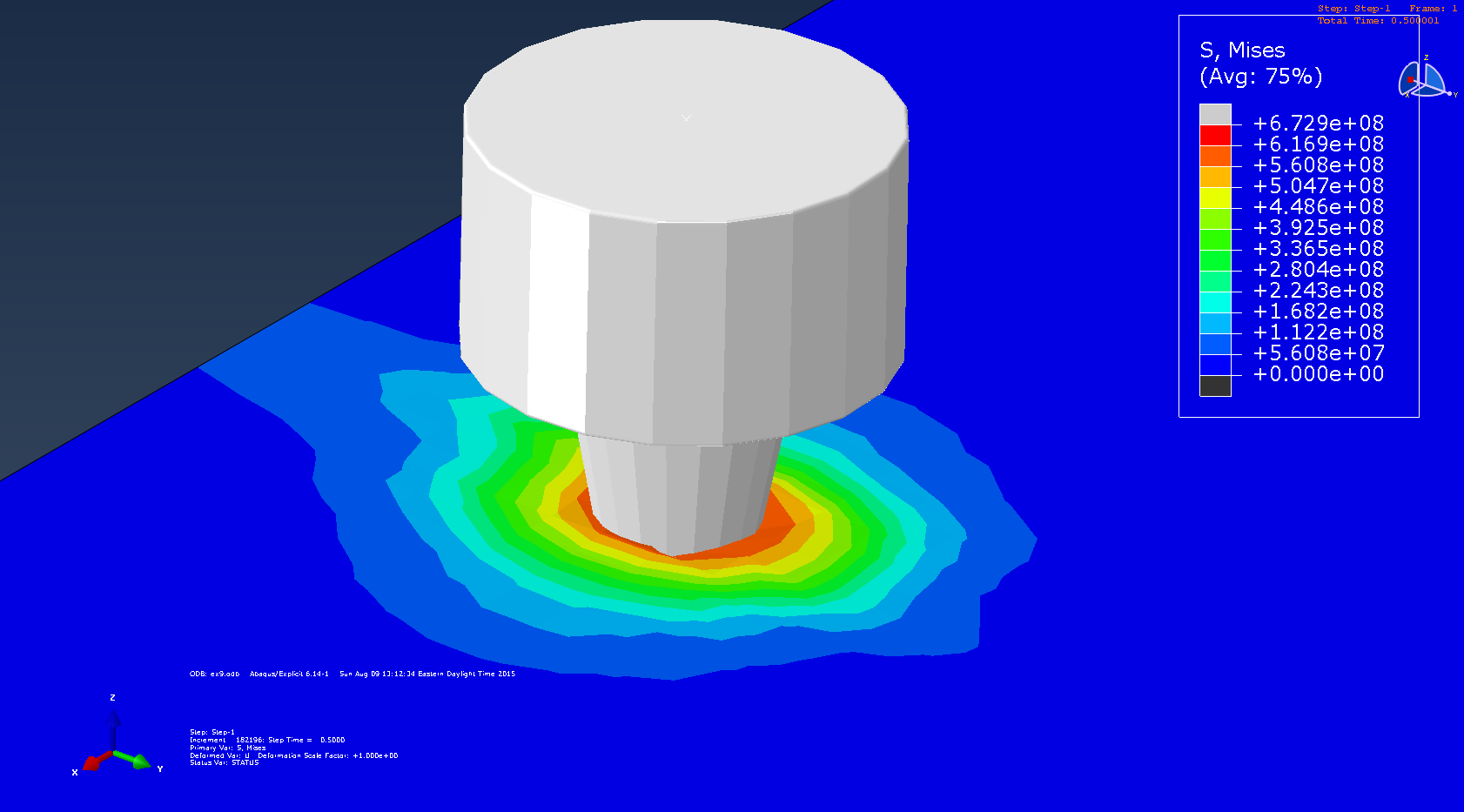
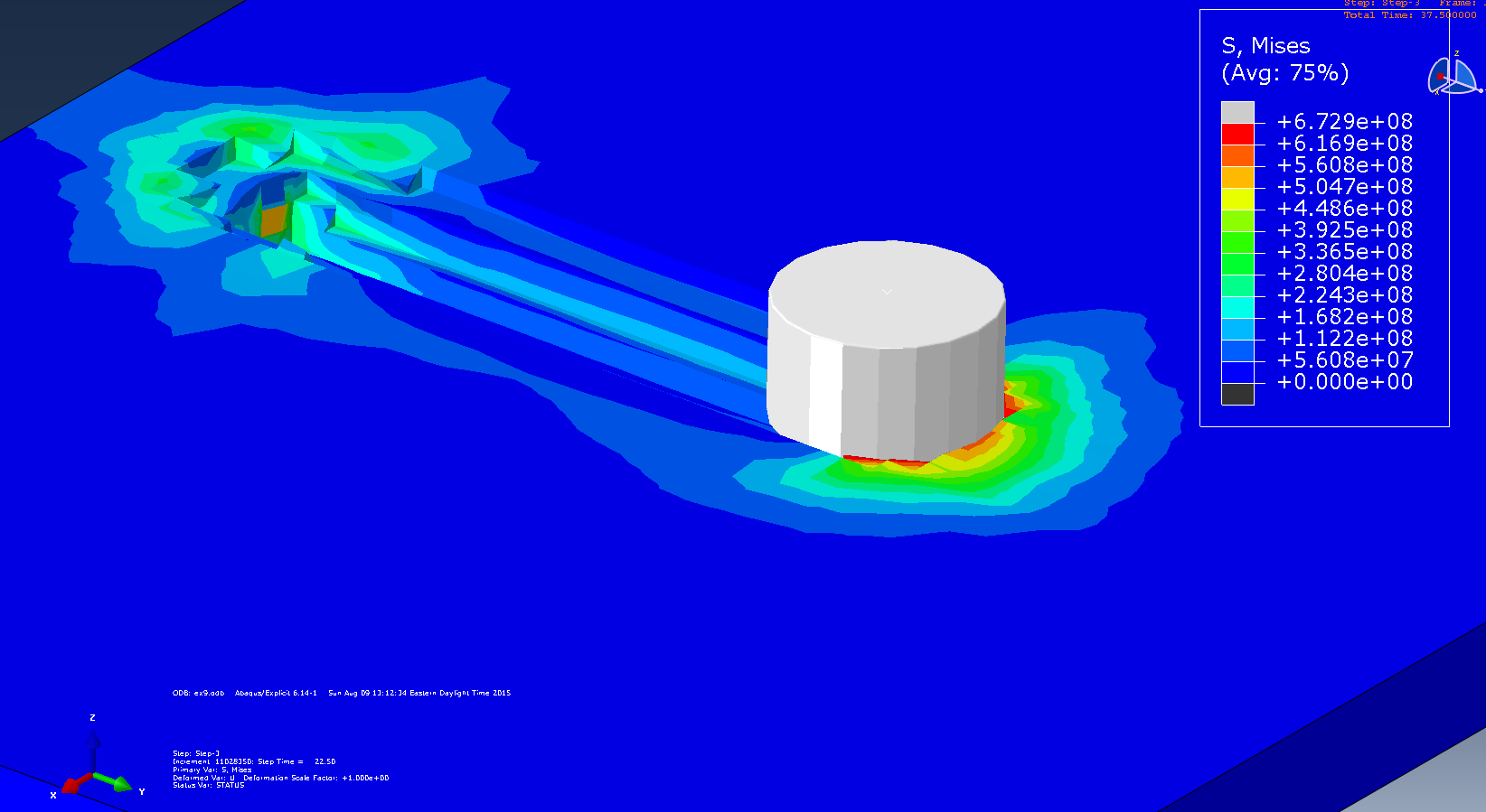
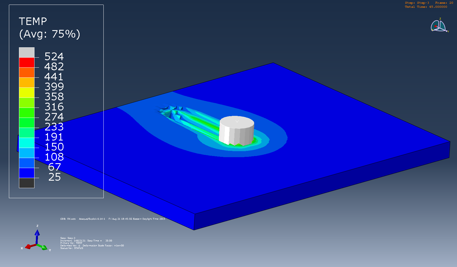
- This project involves modelling of the entire friction stir welding process using ABAQUS.
- FSW is the most common welding technique used to weld aluminum alloys in several automobile and aerospace applications.
- This process involves severe plastic deformation which can be modelled using ABAQUS.
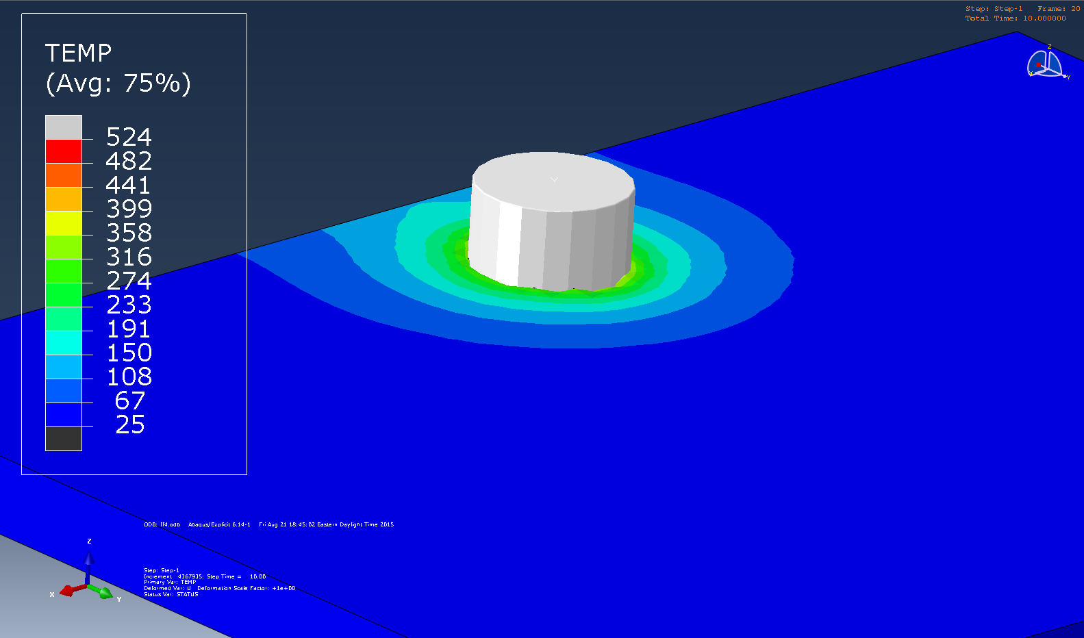
- With this FEM model, we can predict the tool life and set the correct process parameters like plunge force, linear and rotational speed of tool and each process time (plunge, dwell and stir), which helps in cost saving and improving the overall quality of weld.
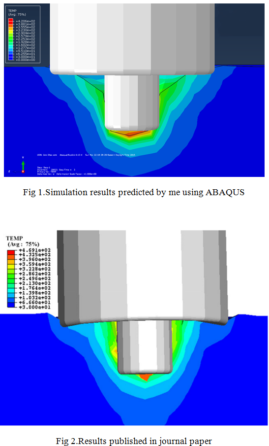
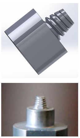
- In this project, the residual stresses formed and the temperature profile developed during the FSW process of most commonly used Aluminum alloys (Al 2024 and Al 7050 grades) have been demonstrated. In addition, since the FSW tool had a complicated geometry (threads along the pin and a concave shoulder), it was first designed using SolidWorks; and later incorporated in the FEM model.
- The results obtained were successfully validated using the experimental data published in scientific journals namely:-
a. "Modelling of entire friction stir welding process by explicit finite element method" by M. Yu, W. Y. Li, J. L. Li and Y. J. Chao, Materials Science and Technology (2012), Vol 28, No 7, 812–817
b. "Experimental and numerical investigation of the plunge stage in friction stir welding" by S. Mandal, J. Rice, A.A. Elmustafa, Journal of Materials Processing Technology, 203 (2008) 411–419
- With a i7 processor , 16 GB RAM, the entire simulation takes about 34 hours to complete!
3. 3D DRILLING MODEL:-
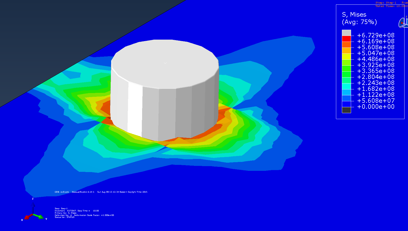
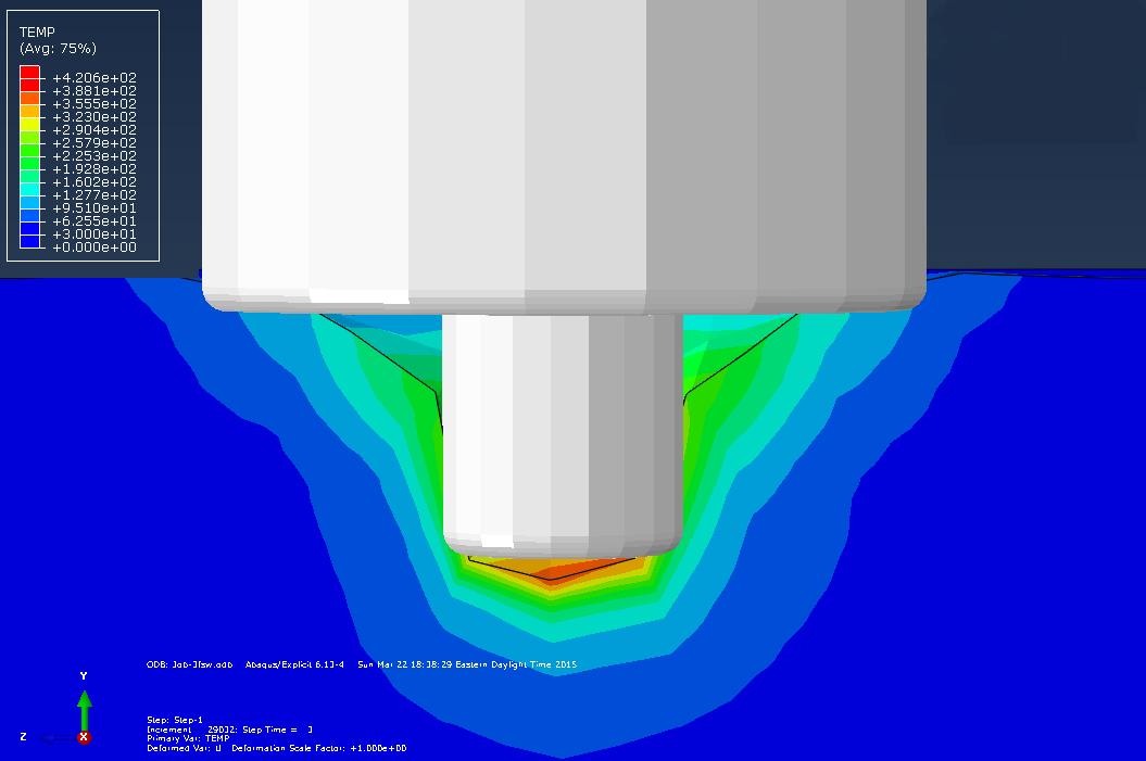
-In this project, the ABAQUS/EXPLICIT FEM software was utilized to simulate the thermo-mechanical behavior in friction drilling of Al 6061-T6 alloy.
-The results have been validated with the results published in the paper “Thermo-Mechanical Finite Element Modeling of the Friction Drilling Process” by Scott F. Miller, Albert J. Shih in the Journal of Manufacturing Science and Engineering, JUNE 2007, Vol. 129 / 531-538
- 3D simulation was chosen instead of two-dimensional 2D, because the work material deforms in the rotational direction
- This FEM model can further be applied to drilling of other Al alloys as well to get the predict the stress distribution profile during drilling.
4. Crack Propagation Model :-
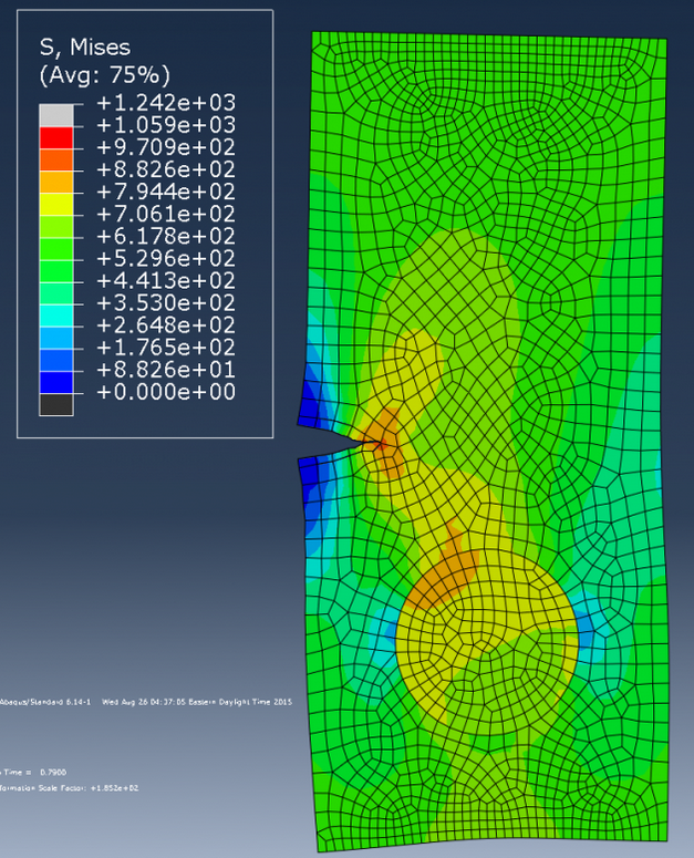
- ABAQUS was used to show how stresses are developed when a crack propagates in a material.
- This example gives a basic understanding in the field of fracture mechanics.
5. Bullet Impact model:-
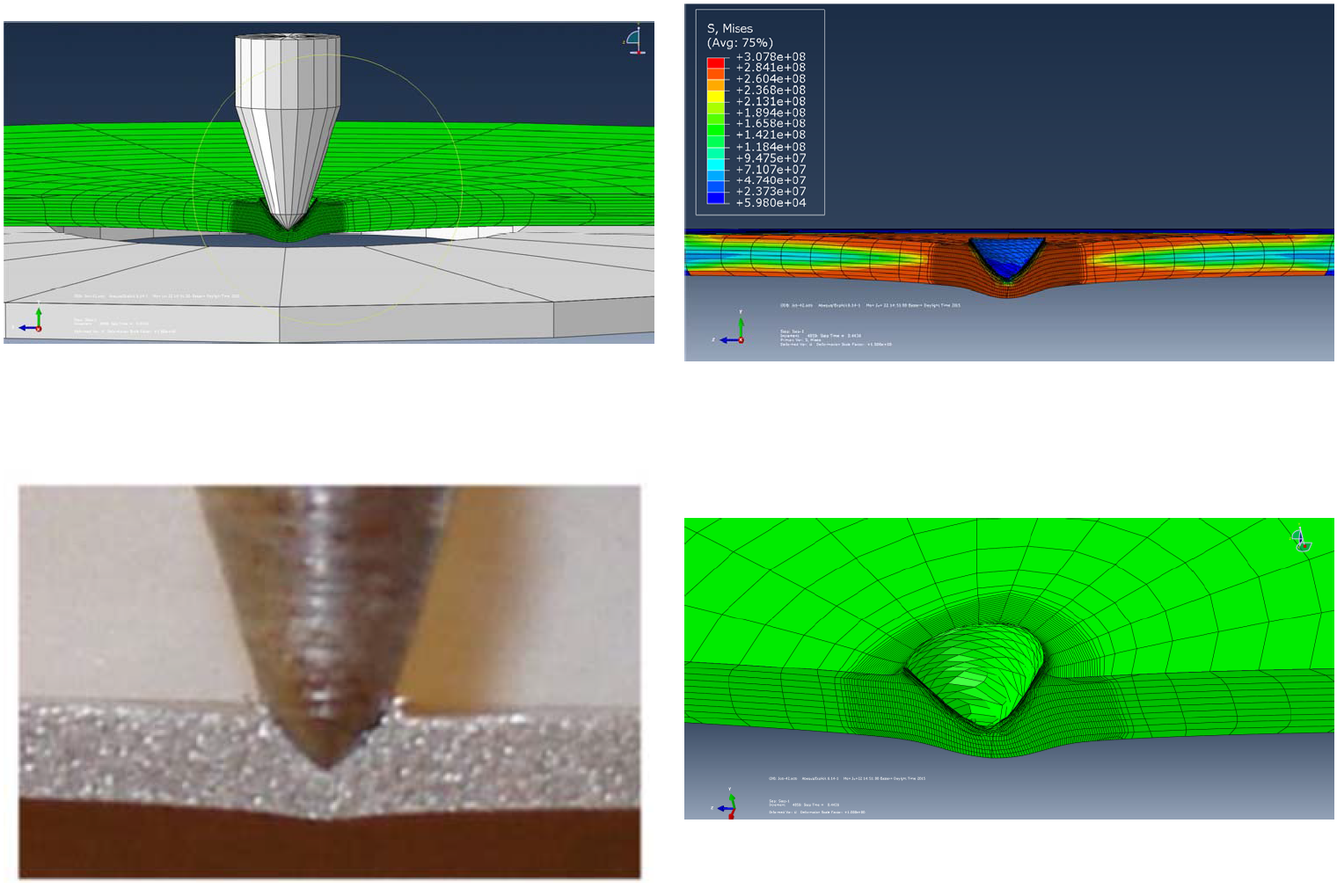
- ABAQUS was used to see the effect of how a bullet travelling at speed of 970 m/s cuts through a Al 6061 plate
- The results obtained were compared with the experimental results from the paper "Aluminum plate perforation : a comparative case study using lagrange with erosion, multi-material ALE and smooth perticle hydrodynamics -- Leonard E Schwer -- Schwer Engineering & Consulting Services Windsor, CA USA"
- The simulation results showed good comparison with the experimental results.
6. Thermal Analysis of Fins used in Automobiles:-
- Understanding how heat transfer takes place in the fins used is very important in determining the cooling rate and the fin design to be employed for cooling of the engines in automobiles.
- In this project, ABAQUS was used as a FEM tool to observe the heat flow of a most commonly used fin design used in automobiles.
7. Crushing Can Model :-
- The process in which a empty can deforms when hit by a plate with a high velocity was observed using ABAQUS. The weight of the plate is 275 kg and it hits the can with a velocity of 15.6 m/s.
- The results obtained were later matched with the observations made in the paper "Design of thin wall structures for energy absorption applications: Enhancement of crashworthiness due to axial and oblique impact forces",F. Tarlochan,, F. Samer , A.M.S. Hamouda , S. Ramesh , Karam Khalid, Thin-Walled Structures 71 (2013) 7–17.
- The simulation results obtained were similar to the observations made in the paper. Hence this FEM Model can be used to observe the deformation of any thin walled structure.
Abhishek Ajri
Purdue University
![Bullet impact on Al 6061 plate (experimental vs simulation) [Cross sectional view] Bullet impact on Al 6061 plate (experimental vs simulation) [Cross sectional view]](/sites/default/files/456-gallery-14406944797451-August%208th%2C%202015.png)

Check my new project